
7 Tips to Choose the Right Crankshaft Bearing?

Choosing the right Crankshaft Bearing is not a simple matter of matching diameter and width. A bearing may fit perfectly and still fail early. Oil clearance, crankshaft finish, load direction, engine temperature, and housing alignment all influence its service life. In a rebuilt engine, one small measurement error can leave a dull scoring mark across the bearing surface.

Dr. Ilia Spassov, a bearing development specialist at King Engine Bearings, emphasizes, “Bearing performance depends on the complete system, not the bearing alone.” This principle guides the seven practical tips in this article. They examine material selection, bearing size, oil clearance, groove design, surface coating, installation accuracy, and operating conditions. Each point connects a workshop decision with a real mechanical consequence.

Look closely at the crankshaft journals before choosing anything. A fingernail catching on a groove is already a warning. Check the housing bore with calibrated measuring tools, not visual judgment. Confirm the manufacturer’s clearance range, then consider the engine’s actual workload. A street engine, racing engine, diesel engine, and restored classic engine may require different solutions.

Some recommendations may appear overly cautious. They are. Bearing failures are often expensive, noisy, and difficult to diagnose afterward. Even experienced builders can overlook dirt behind a shell or confuse a worn crankshaft with a poor-quality Crankshaft Bearing. These tips cannot replace professional measurement. They can, however, reduce guesswork and encourage better decisions before final assembly.
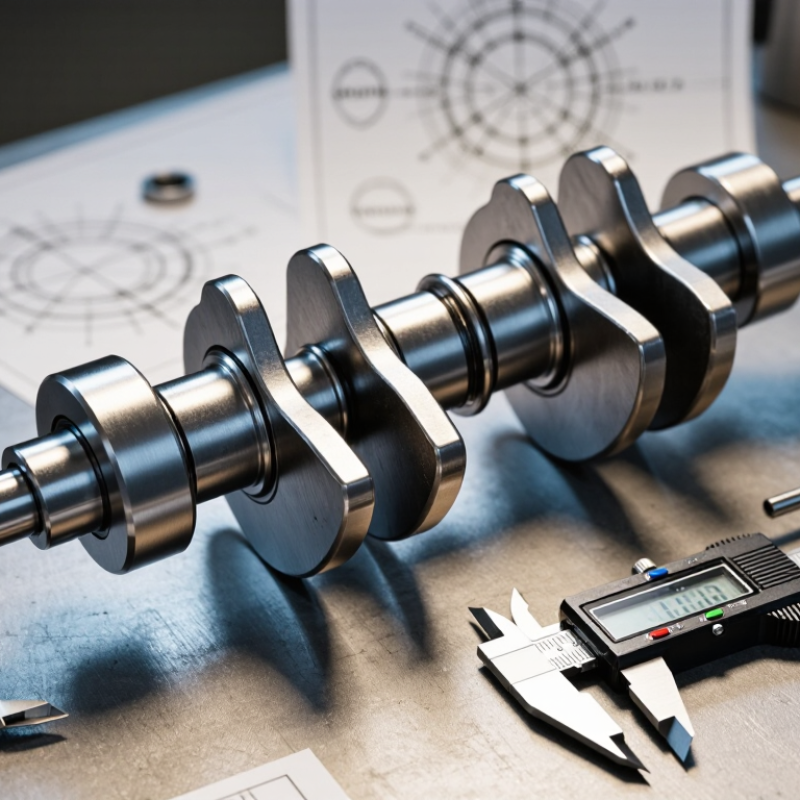
7 Tips to Choose the Right Crankshaft Bearing?

Define Engine Loads, Speed, and Oil Conditions Before Choosing a Bearing

7 Tips to Choose the Right Crankshaft Bearing

Define engine loads, speed, and oil conditions before choosing a crankshaft bearing. Peak cylinder pressure creates the highest bearing load, not average power. Record torque, firing frequency, crankshaft deflection, and expected misalignment. A useful field rule is simple: design around the worst operating event.

Check the full speed range. Bearing behavior changes sharply near idle, overspeed, and rapid acceleration. The U.S. Department of Energy reports that friction can consume about 15% of fuel energy in internal-combustion vehicles. Correct clearance can reduce this loss, but excessive clearance lowers oil-film stiffness. Use SAE J300 viscosity grades and confirm actual viscosity through ASTM D445 testing. Oil temperature matters more than the label on the container. Hot oil becomes thinner. Very cold oil may delay film formation.

Match bearing material and surface structure to the load profile. Review dirt exposure, oil aeration, start-stop cycles, and crankshaft hardness. ISO 4406 cleanliness methods can help quantify particle contamination, although they were not created specifically for engine bearings. Validate the choice with pressure, temperature, and wear measurements. I have seen calculations pass while oil starvation caused damage within minutes. That is the uncomfortable part. Computer models need real test evidence. Recheck assumptions after every failed inspection.

Check Journal Size and Clearance Against OEM Specs and ISO 3548-1

7 Tips to Choose the Right Crankshaft Bearing?

Journal size and oil clearance deserve more attention than bearing appearance. Measure the crankshaft journal with a calibrated micrometer at several points. Check taper, ovality, and surface damage. Then compare the readings with the engine manufacturer’s service limits. Do not rely on a catalog size alone. A bearing marked “standard” can still fail when the journal has been reground or polished.

ISO 3548-1 provides measurement methods for thin-walled half bearings, including bore and wall-thickness checks. It also emphasizes controlled measurement conditions and repeatability. Use a precision bore gauge to verify the assembled bearing bore. Confirm clearance against the OEM specification, not a general rule. A common workshop estimate is about 0.001 inch per inch of journal diameter, but this is only a starting reference. It cannot replace the specified value.

Oil clearance affects pressure, temperature, and film strength. The U.S. Department of Energy’s Vehicle Technologies Office commonly identifies engine friction as roughly 10–15% of fuel-energy losses. Small clearance errors can therefore waste efficiency and accelerate wear. I have seen clean-looking shells fail after assembly. The hidden cause was an unmeasured journal taper. Use measuring instruments twice. A clearance strip can provide a useful cross-check, but it should not be the only evidence. Record every journal reading, bearing size, and measurement temperature. This simple record makes a doubtful decision easier to review.

Match Bearing Materials to Fatigue and Corrosion Needs Under SAE J460

7 Tips to Choose the Right Crankshaft Bearing

Choosing a crankshaft bearing starts with the operating environment, not a catalog number. SAE J460 offers useful guidance for evaluating bearing materials, load capacity, and service conditions. In practice, I compare the standard’s recommendations with oil temperature, shaft speed, contamination, and actual duty cycles. A small mismatch can create wiping, fatigue cracks, or corrosion marks.

Tip: Identify the dominant load. High cylinder pressure needs strong fatigue resistance.

Tip: Check peak temperature, not only average temperature. Heat can soften a lining quickly.

Tip: Match the material to the oil chemistry. Corrosive additives may attack unsuitable surfaces.

Tip: Review shaft alignment carefully. Misalignment concentrates pressure along one edge.

Tip: Consider dirt exposure. Hard particles can score the bearing and damage the crankshaft.

Tip: Confirm clearance under real conditions. Thermal expansion changes it.

Tip: Validate the choice through testing. SAE J460 is a reference, not a substitute for evidence.

Material selection deserves practical judgment. A softer overlay may protect the crankshaft during brief contamination, while a stronger structure may survive repeated loading better. The best balance depends on fatigue, corrosion, embedability, and wear requirements. I have seen specifications look complete while missing cold-start behavior. That gap matters. Inspect used bearings after testing, especially near the parting line and highest-load zone. Record surface discoloration, cracks, and uneven contact. Even experienced engineers can overlook one variable. Examine it again.

Verify Babbitt Alloy Quality and Bond Strength Using ASTM B23 Standards

Choosing the right crankshaft bearing starts with its Babbitt alloy. ASTM B23 provides a recognized reference for white-metal bearing compositions and grades. Confirm the supplier’s material certificate, alloy designation, chemical analysis, and batch traceability. Do not accept “premium alloy” as technical evidence.

The surface should be examined under proper lighting. Look for pores, cracks, inclusions, uneven tinning, or exposed steel. A small cross-section can reveal whether the lining is uniform. Bond strength needs separate attention. ASTM B23 helps verify alloy quality, but it does not prove adhesion by itself. Request an agreed bond-strength test, preparation records, and results from representative samples. Review surface cleaning, tinning temperature, pouring conditions, and bonding pressure. These details often explain failures better than appearance.

Fit matters as much as chemistry. Check bearing clearance, crush, oil grooves, wall thickness, and housing alignment against the engine specification. Ask whether the lining survived dimensional inspection after machining. Thermal cycling and oil compatibility tests can expose weak interfaces early. In one inspection, a bright bearing looked excellent until a cross-section showed a thin, poorly bonded layer. That mistake was avoidable. Keep inspection photographs and signed reports with the batch records. Shortcuts become expensive. A reliable choice combines ASTM B23 compliance, verified adhesion, accurate dimensions, and documented production controls.

Confirm Oil-Film Performance Across the Engine’s Operating Temperature Range

Choosing the right crankshaft bearing starts with its oil-film performance, not a catalog dimension alone. Measure the engine’s real temperature range, from cold starts to sustained high-load operation. Cold starts matter. At low temperatures, oil moves slowly and may delay full journal coverage. At 90–110°C, viscosity falls, changing film thickness and friction. Heat changes everything.

Check bearing clearance against the crankshaft journal size, oil grade, pump pressure, and engine speed. A tighter clearance may support pressure, but it can restrict flow when the oil becomes hot. Excessive clearance may weaken the film during hot idle. Review load cycles, too. Short acceleration bursts and long highway loads create different lubrication demands. Look for data from dynamometer tests or controlled field testing, not only static specifications.

Inspect the bearing surface, edge loading, and wear pattern after testing. A smooth center may hide contact near an edge. That detail deserves attention. I once treated oil pressure as the main indicator, but pressure alone did not prove stable film separation. Temperature, clearance, speed, and load must be read together. Compare results at cold start, normal cruising, hot idle, and maximum permitted load. Do not guess. A practical choice may involve a small compromise between flow, friction, durability, and manufacturing tolerance. Recheck the decision when the engine’s oil, cooling system, or operating profile changes.

7 Tips to Choose the Right Crankshaft Bearing? - Confirm Oil-Film Performance Across the Engine’s Operating Temperature Range

Tip Selection Dimension Reference Data or Engineering Range How to Verify Bearing Selection Implication
1 Map the complete oil-temperature range Typical fully warmed engine-oil temperatures are approximately 80–120 °C. Short-duration high-load operation can raise oil temperature above this range, while cold-start conditions may occur below 0 °C depending on climate. Record sump, gallery, and bearing-area temperatures during cold start, warm-up, high load, and transient operation. Choose a bearing and lubricant combination that maintains adequate film strength at the hottest condition and acceptable flow at the coldest condition.
2 Match lubricant viscosity to the application Common SAE viscosity grades have different kinematic-viscosity limits at 100 °C: 0W-20: 6.9–9.3 mm²/s, 5W-30: 9.3–12.5 mm²/s, and 10W-40: 12.5–16.3 mm²/s. The exact oil specification must follow the engine design requirement. Check the oil specification sheet for viscosity at 40 °C and 100 °C, high-temperature/high-shear viscosity, and viscosity index. Lower viscosity can reduce friction but may reduce film thickness; higher viscosity can improve film strength but increase pumping losses and cold-start resistance.
3 Confirm operating clearance Many automotive plain-bearing applications use diametral clearances roughly within 0.03–0.08 mm, but the correct value depends on journal diameter, speed, load, oil viscosity, housing stiffness, and manufacturer tolerances. Measure crankshaft journals and assembled bearing bores with calibrated micrometers, bore gauges, or an approved clearance-measurement method. Excessive clearance can reduce oil pressure and film thickness; insufficient clearance can cause seizure, overheating, or inadequate oil flow.
4 Evaluate load and speed together Bearing performance is governed by the pressure–velocity relationship. The most demanding points are usually peak combustion load, maximum engine speed, rapid acceleration, and low-speed high-torque operation. Use crank-train analysis or dynamometer data to determine journal load, rotational speed, load direction, and minimum oil-film thickness at each operating point. Select the bearing construction and wall thickness for the highest combined mechanical and thermal duty, not only average engine conditions.
5 Check minimum oil-film thickness A hydrodynamic bearing should maintain a positive separating film under normal operation. A practical design review should compare calculated minimum film thickness with surface roughness and the allowable mixed-lubrication limit; there is no universal film-thickness value for every engine. Use thermohydrodynamic simulation, strain-based testing, or validated engine-test instrumentation across the full temperature and speed map. If the calculated film becomes marginal at high temperature or low speed, review clearance, oil viscosity, bearing geometry, and oil-supply capacity.
6 Verify material compatibility and embedability Common bearing systems include steel-backed multilayer designs with copper-based or aluminum-based intermediate layers and a thin overlay. Material choice affects fatigue strength, seizure resistance, corrosion resistance, and tolerance to small particles. Review material hardness, fatigue capacity, overlay thickness, surface roughness, oil chemistry compatibility, and resistance to debris-induced damage. High-load applications may require stronger fatigue support, while contaminated or less-controlled systems may benefit from greater embedability and conformability.
7 Confirm oil supply, alignment, and thermal control Bearing temperature is affected by oil flow, inlet temperature, groove design, crankshaft alignment, housing deformation, and heat transfer. Oil cleanliness is also critical; commonly used hydraulic cleanliness references classify particle contamination by particle size and count rather than by visual inspection. Check oil pressure and flow at hot idle and rated speed, inspect oil holes and grooves, measure alignment, and analyze used oil for wear metals and contamination. A suitable bearing cannot compensate for restricted oil passages, poor alignment, excessive crank flex, overheating, or contaminated lubricant.
Engineering note: The numerical values shown are general reference ranges for preliminary screening. Final crankshaft-bearing selection must be validated against the engine manufacturer’s dimensional tolerances, lubricant specification, load map, temperature profile, and durability-test results.
Skip to content